MeddieMakes - Unnamed T-Trak Modular Layout
 MeddieMakes (Craig)Started 25 April 2026
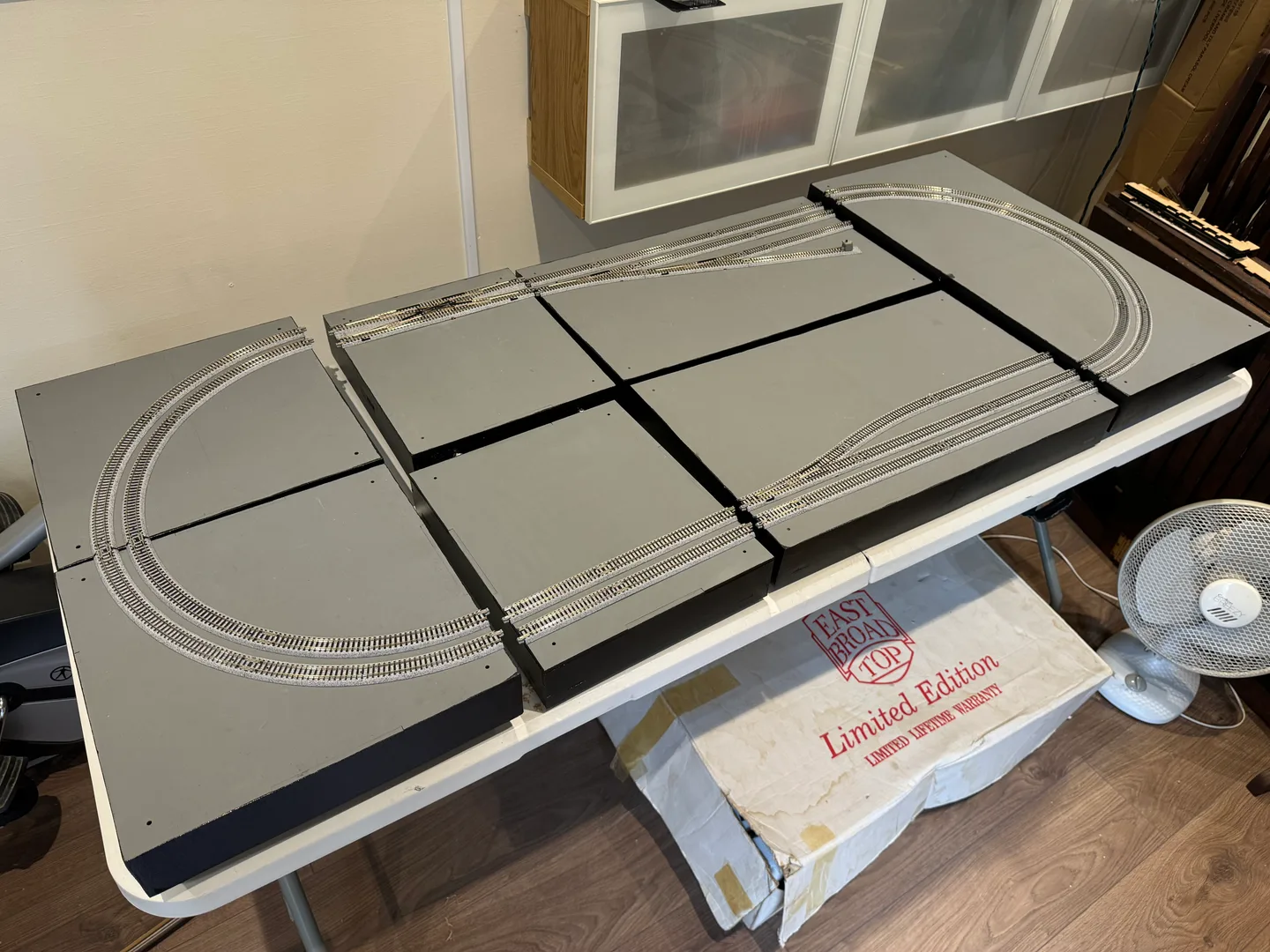
I’m building an N gauge layout that is currently in the early stages of construction. Designed as an exhibition layout, it will feature a series of sections inspired by some of the UK’s most recognisable landscapes and locations, with each set of modules representing its own unique theme. Built to T-Trak standards, the modules can be displayed individually as smaller layouts or connected together to create an ever-expanding larger layout. This flexible approach allows the railway to grow over time while offering a variety of display options. The layout will use Kato Unitrack throughout, in keeping with T-Trak standards, meaning it can also be linked with other compatible modules by other modellers or clubs. The modules themselves are handcrafted by me and will also be available to purchase through my website at https://meddiemakes.co.uk Although the project is still in its early stages, I will be documenting the layout models here on RateMyRailway and on the MeddieMakes website.
T-Trak DCC-EX Power Module Build - Wiring Complete
Quick update on the T-Trak DCC-EX power module build: it’s now fully completed and up and running 🎉
Really happy with how this turned out overall. The enclosure went together nicely, all the panel cut-outs lined up properly, and the wiring behaved itself enough to avoid becoming a bowl of electronic spaghetti. The display, USB access, and track outputs are all working exactly as intended, and it now has that proper “mini control console” feel sitting on the layout.
Only one small tweak left on the to-do list: the Track A/B indicator LEDs are a little brighter than expected at full power. Nothing major, but I’ll likely increase the resistor values slightly to tone them down a bit and make the indicators a little easier on the eyes during operation.
Apart from that, the project has gone smoothly from start to finish and I’m really pleased with the final result 👍
Features:
Front Panel
Track A (Red Line - Front Track) - DCC-EX Output 1
Track B (Yellow Line - Rear Track) - DCC-EX Output 2
Power Indicator (Blue LED) for DCC-EX System
Track Polarity Indicator for Track A / B (Green - DC Forward, Red - DC Backwards, Yellow - DCC)
USB Type B for updating DCC-EX or to plug into a PC for JMRI or EX‑WebThrottle
Rear Panel
Isolation Power Switch on Back Panel to disable DCC-EX Command station, Allows module to be added to a layout as a standard single module
12V (Limited to 5A) Accessory Output to power other modules (Including Kato point motors) example coming soon
Track A / B outputs (Phono Connector) for interconnecting additional power feeds to other modules
Now to try all the different DCC-EX phone apps to see which I prefer and I may also look into custom physical DCC-EX mini throttle for that more tactile controller in the future.
If you have used DCC-EX, Please let me know in the comments, would be great to hear about your experience and what controller you use.
T-Trak DCC-EX Power Module Build
Thought I’d share a quick build log of the DCC-EX power module I’ve just started putting together for my T-Trak setup.
First Look
I have designed a power module with a separate white MDF facia panel based on my laser-cut MDF single module. Everything is tab-and-slot, so it’s basically a very satisfying 3D jigsaw. The facia panel is currently temporarily secured with masking tape, as I currently review different methods to secure the facia to the module frame.
Considered using submerged magnets or screws to allow the fascia to be removed for maintenance but this might be overkill as there is plenty of room under the module to access the back of the components. Front panel is already engraved and labelled, giving the facia a great professional look, which is a big win:
Screen cut-out (2.4” LCD Screen)
LEDs for DCC-EX power + Track A/B (Bicolor LED for polarity indicator)
USB port access for updating DCC-EX So no guessing what goes where, which is always appreciated.
Dry Fit
I always like to test-fit before committing to glue, and this went together really nicely. The tolerances are tight but not “force it and regret it” tight.
Here’s where I’m at so far:
Base + sides slotted together cleanly
Front panel lined up perfectly with all cut-outs
Back panel sits upright and gives it a nice solid shape
Layout Planning
Before gluing it up, I’m taking a minute to think about internals:
Where the DCC-EX board will sit
Cable routing for Track A / Track B
Making sure the USB port lines up properly and doesn’t interfere with the adjustable legs
Leaving enough room so wiring doesn’t turn into spaghetti Next Steps Next job will be installing the front panel components:
Wire up the display behind the cut-out
Fit LEDs into their positions
Line up the USB port After that, I’ll glue the enclosure together and start wiring everything up.
Thoughts So Far
I really liked the progress so far. Everything lines up the way I'd hoped, and it already looks like it’s going to be a neat little control unit when finished. Kind of has that “tiny command centre” vibe going on. I’ll update once I’ve got the electronics in and powered up 👍
Edited 30 Apr at 12:46
Build Stats
Layout Specifications
Linked Layout
MeddieMakes - Unnamed T-Trak Module Layout
N (1:160)
Comments (0)
Community Guidelines
Keep all comments friendly. Feedback should be constructive and no derogatory comments are tolerated.
Sign in to join the conversation
No comments yet
Be the first to share your thoughts!