DCC Model Railway Wiring Guide

One of the quickest ways to spoil a good operating session is unreliable power. A locomotive hesitates over a point, sound drops out on the far side of the layout, or a short shuts the whole railway down just as you are enjoying yourself. That is exactly why a solid DCC model railway wiring guide matters - not because wiring is glamorous, but because good wiring makes everything else feel better.
DCC can look intimidating at first because it asks you to think differently from simple analogue cab control. Instead of splitting the railway into lots of isolated sections for normal operation, you are feeding digital power to the whole layout and letting each decoder respond to its own address. In practice, that often means the track wiring is simpler in one sense and more demanding in another. Simpler, because you usually need fewer switching sections. More demanding, because weak joints, poor feeds and casual wiring habits show up very quickly.
DCC model railway wiring guide - start with the bus
The backbone of most DCC layouts is the power bus. This is a pair of heavier wires running beneath the baseboards, carrying the command station or booster output around the layout. Think of it as the main supply line. The rails are not meant to carry power reliably over long distances on their own, especially once fishplates loosen, oxidation appears or boards are joined and separated a few times.
For most home layouts, a pair of reasonably stout wires is enough for the bus. The exact size depends on layout length and current draw, but going heavier than you think you need is rarely a mistake. Under-baseboard access is awkward enough without rewiring later because voltage drop has become a nuisance.
Keep the two bus wires clearly identifiable from the start. Many modellers use one colour for the left rail and another for the right rail, and they stick to that convention across the whole railway. That sounds obvious, but consistency is what stops accidental crossovers, mystery shorts and head-scratching fault-finding six months later.
Why droppers matter more than many beginners expect
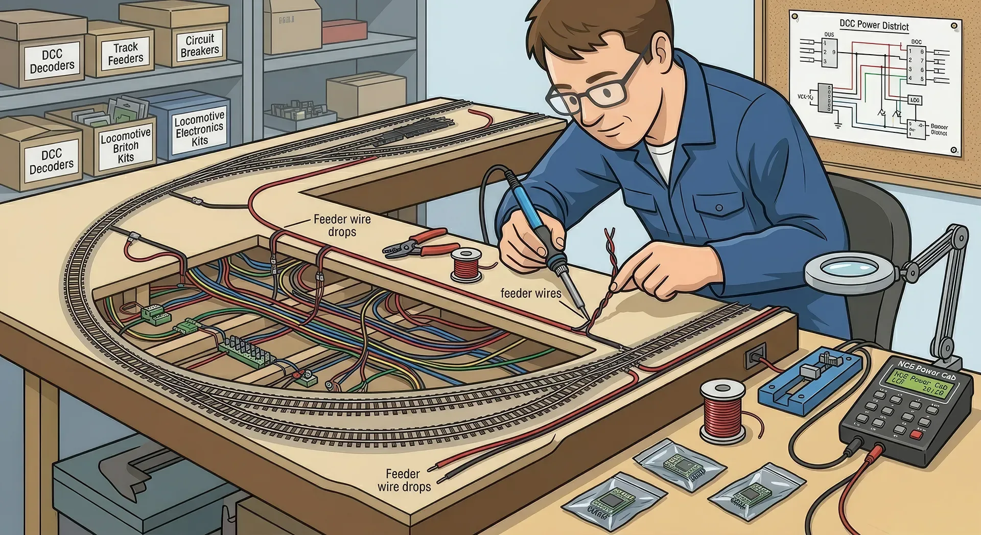
If there is one habit that improves DCC reliability more than almost anything else, it is fitting regular droppers. A dropper is a short wire from each rail, or at least each length or section of track, down to the power bus below. The bus distributes power, and the droppers deliver it directly where it is needed.
Relying on rail joiners alone may work for a while on a small test oval. On a permanent layout, particularly one with scenic work, hidden sidings or multiple boards, it becomes a weak point. Joiners loosen, dirt builds up, and expansion or movement causes tiny breaks in continuity that DCC decoders notice straight away.
There is some judgement involved here. A compact shunting plank may not need a dropper to every single piece of track if the rail lengths are short and all joints are sound. A larger layout absolutely benefits from frequent feeds. Many experienced builders simply wire every section from the outset because it removes doubt later.
Keep droppers short where possible, and solder them neatly to the rails. If you can hide them beside chairs or on the inside of the rail where they will vanish once painted and ballasted, even better. What matters most, though, is that each wire is electrically sound and connected to the correct side of the bus.
Points, frogs and the question of live or insulated crossings
Points are where DCC wiring stops being repetitive and starts becoming layout-specific. Not all pointwork is wired the same way, and much depends on whether you are using insulated frog points, live frog points or a system with built-in switching.
Insulated frog points are usually easier for beginners. They reduce the wiring complexity because the frog area is electrically dead, which removes one switching requirement. The trade-off is that very short wheelbase locomotives can hesitate or stall at slow speed, especially if the point is slightly dirty.
Live frog points usually offer better running, particularly for shunters, tank engines and anything creeping through yards. The trade-off is that they need frog polarity switching, whether by a point motor switch, an accessory switch or an electronic device. If the frog is not switched correctly, you will get immediate shorts or dead sections.
This is the point where following the manufacturer diagram matters. Even among experienced modellers, wiring assumptions cause problems because one brand's point may not behave like another's. If you are mixing track systems on the same layout, be even more cautious.
Reverse loops need planning, not guesswork
Sooner or later, many DCC builders want a reverse loop, turning triangle or wye. These track arrangements are excellent for operation because they let trains turn or re-enter the layout facing the other way. Electrically, though, they create a polarity conflict.
On a DC layout, reverse loops also need special treatment, but DCC has made them more manageable thanks to auto-reversers. These devices detect the short the moment wheels bridge the boundary and swap the polarity almost instantly. When set up properly, the train usually passes through without drama.
The key is to isolate the reversing section fully at both ends and make sure the isolated section is long enough. If the section is shorter than your train or locomotive wheelbase arrangement effectively requires, you can get awkward bridging and repeated shorts. This is one of those areas where a sketch before you wire saves a lot of frustration underneath the boards.
Accessory wiring is best kept separate where practical
A common beginner mistake is treating all layout wiring as one big bundle. Track power, point motors, lighting, building illumination and accessory decoders can end up sharing routes in a way that makes later changes miserable. A cleaner approach is to separate track bus wiring from accessory wiring as much as practical.
That does not mean everything must be over-engineered. It simply means labelling wires, grouping them logically and leaving room to trace a fault later. If your point motors use a separate power supply, that can also reduce strain on the DCC system itself. The same goes for lighting circuits and animated features.
For larger layouts, terminal blocks and labelled connection points are worth the effort. They are not exciting to install, but they make board joins, maintenance and alterations far easier. Exhibition layouts, modular setups and anything likely to be moved benefit especially from that discipline.
Good wiring habits make fault-finding much easier
Most DCC wiring problems are not mysterious. They usually come down to one of a few familiar culprits: a reversed pair of droppers, a point frog wired incorrectly, a missed insulating joiner, a metal tool left across the rails, or a poor solder joint that only fails intermittently.
The trouble is that once the underside of a layout fills up with similar-looking wires, even a simple error can become hard to spot. That is why good habits matter. Label your bus runs. Use consistent colours. Test each section as you build rather than finishing all the wiring and hoping for the best.
A basic continuity tester or multimeter is invaluable. So is a methodical approach. If a short appears after you wired one new yard throat, start there. If a dead section begins just beyond a board joint, inspect that joint first. Fault-finding is slower when you assume the worst and faster when you narrow the problem down step by step.
Small layouts and large layouts need different levels of rigour
A compact end-to-end branch terminus in OO or N can be wired very simply for DCC and work beautifully. A large loft layout with hidden staging, multiple operators and sound-fitted locomotives needs a more deliberate electrical plan. The principles are the same, but the margin for casual wiring gets smaller as the railway grows.
That is worth remembering because many wiring guides make every project sound equally complex. It depends on the layout. If yours is modest, do not overcomplicate it. If yours is ambitious, do not underspecify it because a tiny shunting plank online seemed to get away with minimal feeds.
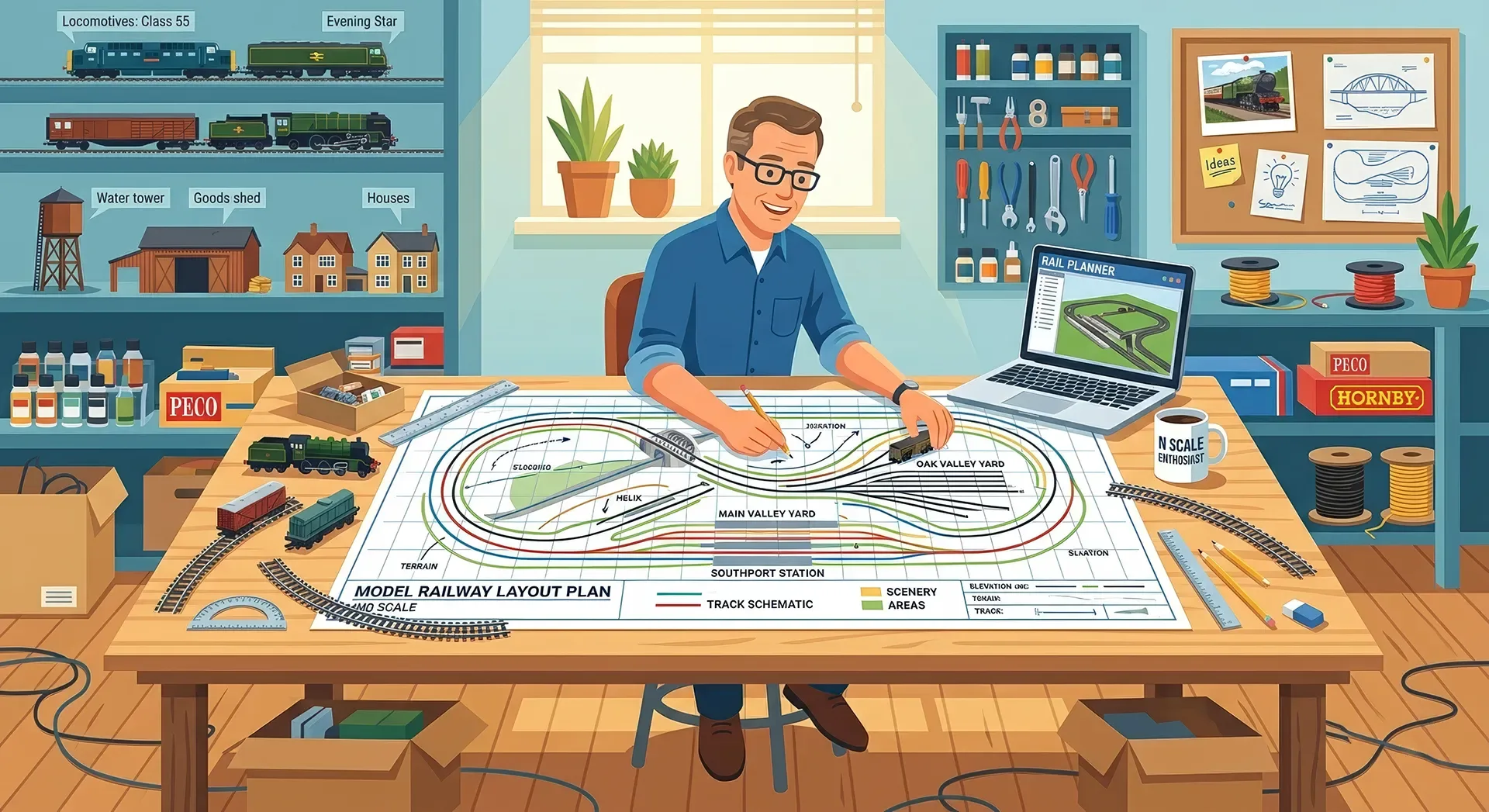
For that reason, many builders like to sketch the track plan and mark the bus routes, droppers, isolating gaps, point feeds and accessory zones before touching the soldering iron. It is not about making the hobby feel like engineering homework. It is about avoiding the sort of hidden mistake that only appears once ballast, buildings and scenery are in place.
A practical DCC model railway wiring guide for first-time builders
If you are wiring your first DCC layout, the sensible route is usually this: install a clear two-wire bus, add frequent droppers, wire and test one area at a time, and treat points and reverse loops as special cases that deserve proper diagrams. Keep accessory power organised separately where possible, and resist the temptation to rush the hidden parts because nobody will see them.
That last part matters. On community build logs, including those shared by modellers on ModelRailwayLayouts.com, the layouts that run well year after year are rarely the ones with the most dramatic underside photography. They are the ones built with consistency. Neat enough to understand, sturdy enough to trust, and simple enough to repair.
A good layout does not need perfect wiring. It needs wiring that suits its track plan, current draw, operating style and future maintenance. Build for reliability first, and your railway will reward you every time a train glides through the fiddliest bit of pointwork without a flicker.
Related Posts

Comments (0)
Community Guidelines
Keep all comments friendly. Feedback should be constructive and no derogatory comments are tolerated.
Sign in to join the conversation
No comments yet
Be the first to share your thoughts!