How to Wire a Model Railway Layout

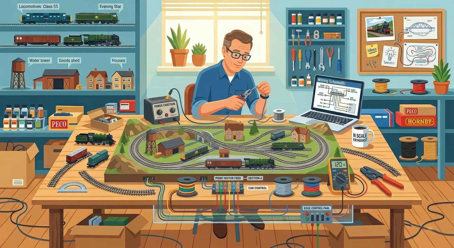
The first time you run a locomotive over freshly laid track and it stalls on a point, slows on a curve, or shorts the whole layout, you find out quickly that trackwork is only half the job. If you are wondering how to wire a model railway layout properly, the good news is that good wiring is less about clever tricks and more about a tidy, repeatable system.
For most layouts, the best approach is to think in layers. Power has to get from the controller to the rails reliably. Points and crossings need to switch without causing dead sections or shorts. Accessories such as lighting, signals and point motors should usually be kept separate from track power. Once you break the job into those parts, wiring becomes far less intimidating.
How to wire a model railway layout without future headaches
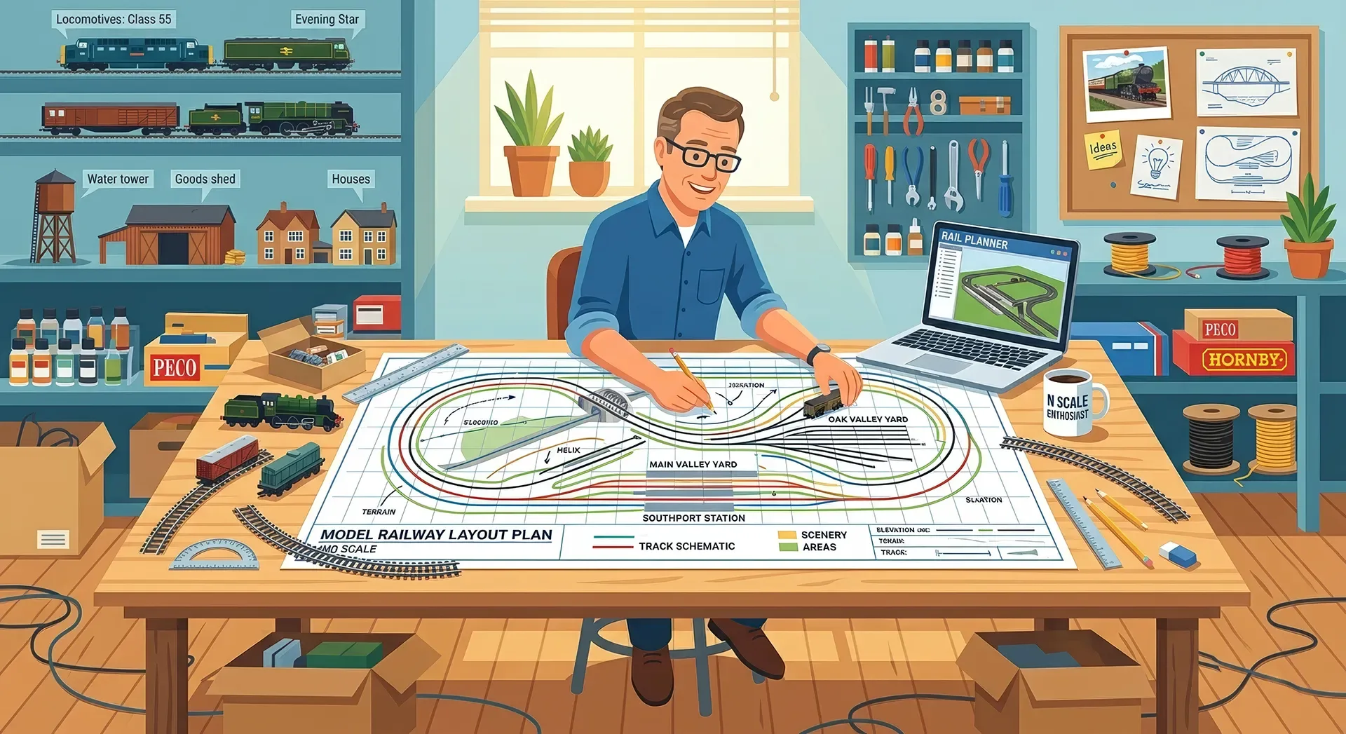
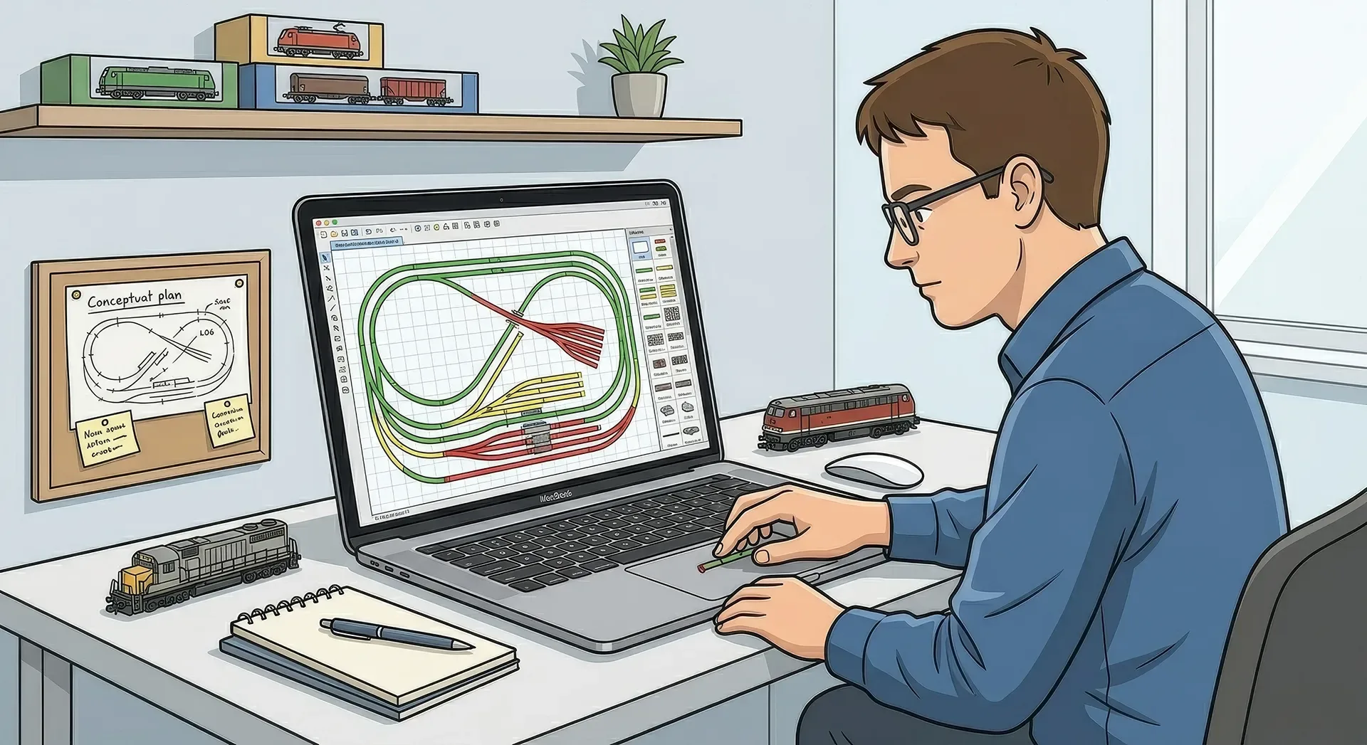
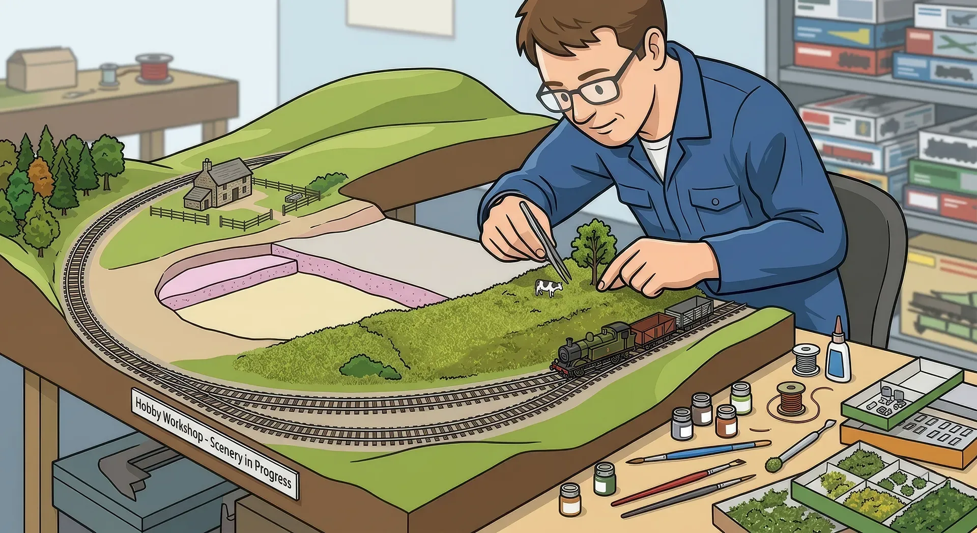
The biggest mistake beginners make is treating wiring as something to add at the very end. It is much easier to plan it while the baseboard is still accessible and before scenery goes anywhere near the track. A simple sketch of the layout, showing power feeds, isolating sections, points and accessory locations, can save hours later.
You do not need a beautiful schematic worthy of an electrical engineer. You do need consistency. Decide early which wire colour means what, where your controller will sit, and whether you are wiring for DC or DCC. That single decision changes quite a lot.
With traditional DC control, you are usually managing sections so that more than one train can be operated independently. That means isolated track sections, section switches and a bit more thought about where one train can be held while another moves. With DCC, the rails are usually live throughout and the decoder in the locomotive handles control, so the focus shifts towards solid power delivery and short-circuit management.
Start with the power bus and droppers
If there is one habit worth adopting on almost every permanent layout, it is using a power bus with droppers rather than relying on fishplates to carry current. Fishplates are for mechanical alignment first. They may conduct power for a while, but oxidation, paint, glue and simple wear all conspire against them.
A power bus is simply a pair of heavier wires running beneath the layout, roughly following the track plan. Each rail is then connected to that bus by short feeder wires, usually called droppers. This gives electricity a dependable route and avoids voltage loss around the layout.
For a small plank or shunting layout, one pair of feeds may be enough, especially if track lengths are short and joints are clean. For anything larger, droppers to every length of track or at least every few sections are the safer option. It feels like overkill when you are doing it, but very few modellers regret adding too many feeds.
Keep the bus wires reasonably heavy compared with the droppers. The exact wire size depends on the layout length and control system, but the principle is simple: the longer the run and the higher the current demand, the heavier the bus should be. Droppers can be thinner because they are short.
Colour coding helps enormously. For example, one rail can always be red and the other black. Keep that convention everywhere, including hidden track. When fault-finding months later, you will thank yourself.
Soldering droppers cleanly
Many builders dislike soldering to visible rail, mostly because a poor joint stands out. The neatest method is often to solder the dropper to the side or underside of the rail before the track is fully fixed down, then feed the wire through a small hole in the baseboard. A quick, hot solder joint is better than lingering too long and melting sleepers.
If your track is already laid, you can still do it neatly. Clean the rail first, use flux sparingly if appropriate, and keep the joint low and discreet so ballast can hide it later.
DC section wiring versus DCC wiring
This is where many articles become vague, but the choice really matters.
With DC, wiring is about control blocks. If you want to park one train in a loop while another keeps moving, those sections need to be electrically isolated and switched. Common return wiring can work, but many modellers prefer fully isolated sections because it is easier to understand and often easier to fault-find. Cab control, where different controllers can be assigned to different sections, is still perfectly valid if you enjoy operating more than one train conventionally.
With DCC, the default aim is even power everywhere. The bus and dropper method comes into its own here. Every locomotive decoder expects a consistent supply, and DCC signal quality can suffer when power is patchy. Reverse loops, wyes and turntables need special attention because rail polarity conflicts can create an instant short. In those cases, an auto-reverser or carefully switched isolated section is the usual answer.
Neither system is automatically better in every situation. DC can be simpler and cheaper for a small layout with one or two trains. DCC offers greater operating freedom, but it rewards careful wiring and can become costly once sound decoders and accessory control enter the picture.
Points, frogs and why stalls happen
If locomotives hesitate on points, the frog is often the culprit. Insulated frog points are straightforward and forgiving, but some short-wheelbase locomotives may stall if the dead frog is too long. Live frog, or electrofrog-style, points improve pickup through the crossing but need more careful wiring.
When wiring live frog points, the frog polarity must change with the route set. That can be done by a switch attached to the point motor, a micro-switch, or an electronic accessory designed for the job. The reward is better slow-speed running. The trade-off is more complexity and more opportunities for a wiring error if you rush it.
You also need to watch for power-routing behaviour. Some points pass current only to the selected route, while others keep both routes live depending on how they are modified or wired. That affects sidings, storage roads and any place where you expect a locomotive to stay put.
Insulated rail joiners where they matter
Not every point needs insulated joiners, but some absolutely do. Crossovers, slips, reverse loops and certain live frog arrangements can create shorts if rails of opposite polarity meet. The track manufacturer's wiring notes are worth following here because point design varies more than many beginners realise.
Keep accessories separate where possible
A reliable layout is usually one where track power and accessory power are not muddled together. Point motors, building lights, signal circuits and animation can create electrical noise or simply draw current you would rather reserve for trains.
That does not mean you need a complicated control panel from day one. It means giving accessories their own supply if possible, or at least their own planned wiring runs. If a point motor misbehaves, you do not want it dragging down the railway every time you throw a switch.
For lighting, think ahead about maintenance. LEDs are efficient and long-lasting, but every lit building still adds wiring. Grouping circuits sensibly under the baseboard makes later changes much easier.
Make the underside as tidy as the scenic side
Under-baseboard wiring rarely appears in glamour shots, yet it often tells you how dependable a layout will be. Clip wires neatly, label important runs, and leave enough slack that components can be changed without tearing everything out. Terminal blocks, plug-and-socket connectors and labelled switch panels are not glamorous either, but they make expansion much easier.
This matters even more on exhibition layouts or modular boards. If boards have to separate for transport, plan connectors early and make sure every joint is obvious, secure and repeatable. A layout that assembles quickly and works first time is always more enjoyable to operate.
If you document your build on a community platform such as ModelRailwayLayouts.com, wiring photos are worth sharing alongside scenic progress. Other modellers often learn just as much from a clean underside shot as from the finished station area above.
Testing and fault-finding as you go
The fastest route to frustration is wiring the whole layout, switching on, and hoping for the best. Test in stages. After each section of track is laid and wired, run a locomotive through it slowly. Check every point in both directions. Confirm that rail polarity is what you expect before moving on.
A simple multimeter is invaluable. You do not need to become an electronics expert, but being able to test continuity and voltage will help you find bad joints, missed breaks and accidental shorts far more quickly than guesswork will.
When something goes wrong, start simple. Look for reversed droppers, point blades touching where they should not, stray strands of wire, or insulated joiners placed on the wrong rails. Most faults are mundane. The trick is being methodical rather than immediately tearing half the layout apart.
A sensible standard beats a clever one
There are endless wiring variations in the hobby, and experienced builders often have strong preferences. Some use control panels full of toggles, some rely on DCC accessory decoders, and some keep everything beautifully minimalist. All of those approaches can work.
What matters most is choosing a system you understand well enough to maintain. If someone else has to decipher it every time you have a fault, it is probably too clever. A model railway should be enjoyable to build, enjoyable to run, and repairable when real life, dust and time get involved.
Wire it neatly, test it in stages, and leave yourself room to change your mind later. That is usually the difference between a layout that merely runs and one that keeps running.
Related Posts
Comments (0)
Community Guidelines
Keep all comments friendly. Feedback should be constructive and no derogatory comments are tolerated.
Sign in to join the conversation
No comments yet
Be the first to share your thoughts!